Description
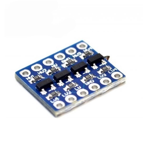
The 4-Channel Bi-Directional Logic Level Shifter is an essential, pocket-sized utility board designed to safely bridge the voltage communication gap between incompatible microcontrollers and peripherals.
Different development platforms run on different voltage architectures—for example, a classic Arduino UNO operates on 5V, while modern chips like the ESP32, Raspberry Pi, and STM32 operate on 3.3V. Connecting a 5V data line directly to a 3.3V pin can permanently fry your sensitive components. This module solves that problem entirely by stepping down high-voltage (5V) signals to low-voltage (3.3V) signals, and stepping up low-voltage signals to high-voltage signals simultaneously across 4 independent channels.
Utilizing high-speed N-channel field-effect transistors (MOSFETs) with integrated pull-up resistors, this board supports truly bi-directional data flow. It automatically handles changing data directions without requiring a directional control pin, making it perfect for high-speed digital communication protocols like I2C, SPI, UART, and standard GPIO switching.
- True Bi-Directional Shifting: Seamlessly converts signals from high-to-low and low-to-high configurations simultaneously without manual direction switching.
- 4 Independent Channels: Safely routes up to 4 distinct data lines (perfect for handling dual I2C buses or complete SPI layouts).
- Multi-Voltage Compatibility: Though optimized for 5V and 3.3V matching, it can reliably shift signals down to 1.8V for ultra-low-power electronics.
- Protocol Friendly: Fully compatible with open-drain architectures like I2C, thanks to its onboard 10k pull-up resistors.
Technical Specifications:
| Parameter |
Specification |
| Channels |
4 Independent Bi-Directional Channels |
| High-Voltage Side (HV) |
Accepts 3.0V to 5.5V DC (Typically connected to 5V) |
| Low-Voltage Side (LV) |
Accepts 1.5V to 3.8V DC (Typically connected to 3.3V) |
| Onboard Pull-up Resistors |
Integrated $10\text{ k}\Omega$ resistors on all 4 lines |
| Maximum Data Rate |
Up to 2 Mbps (Perfect for I2C and UART; standard SPI speeds supported) |
| Breadboard Friendly |
Standard 2.54mm (0.1″) pin pitch layout |
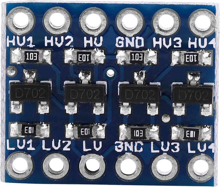
High-Voltage Side (HV)
- HV: Connect to your High-Voltage system power supply (e.g., 5V).
- GND: Connect to your High-Voltage system Ground.
- HV1 / HV2 / HV3 / HV4: High-voltage digital data input/output pins.
Low-Voltage Side (LV)
- LV: Connect to your Low-Voltage system power supply (e.g., 3.3V).
- GND: Connect to your Low-Voltage system Ground (Note: The HV and LV ground pins must be tied together to share a common reference).
- LV1 / LV2 / LV3 / LV4: Low-voltage digital data input/output pins matching the corresponding HV channels.
Quick Connection Example:
- To connect a 5V Arduino to a 3.3V sensor via I2C:
- Connect Arduino 5V to HV, and GND to GND.
- Connect Sensor 3.3V to LV, and GND to GND.
- Route Arduino SDA to HV1 —> Sensor SDA connects to LV1.
- Route Arduino SCL to HV2 —> Sensor SCL connects to LV2.
Reviews
There are no reviews yet.