Description
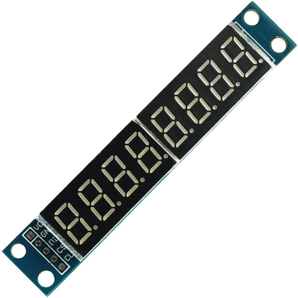
The MAX7219 8-Digit 7-Segment LED Display Module is a compact, easy-to-use serial input/output common-cathode display driver that interfaces microcontrollers to 7-segment digital LED displays.
Featuring the powerful MAX7219 IC, this module allows you to control a full 8-digit numeric display using only 3 data lines (DIN, CS, CLK). This saves dozens of valuable GPIO pins on your Arduino, ESP32, Raspberry Pi, or STM32 development boards. Each digit can be addressed individually, and the onboard display updates smoothly without flickering, thanks to an integrated BCD code-B decoder, multiplex scan circuitry, and internal segment drivers.
A convenient, single external resistor sets the panel brightness, preventing uneven lighting across segments. Additionally, the module supports a low-power shutdown mode, making it an excellent choice for power-sensitive IoT projects, digital clocks, counters, panel meters, and custom electronic dashboards.
- Minimal Pin Count: Controls 8 numeric digits using just 3 digital I/O pins via an SPI-like serial interface.
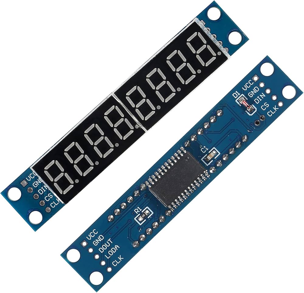
- Cascade Support: Includes input and output pin headers, allowing multiple modules to be daisy-chained together to create larger displays.
- Flicker-Free Operation: Integrated 150µA low-power shutdown mode and hardware-driven multiplexing handle the display refresh entirely on-chip, freeing up your MCU’s processing power.
- Flexible Formatting: Easily display numbers, decimals, negative signs, and select alpha characters
Technical Specifications:
| Parameter |
Specification |
| Driver IC |
MAX7219 (Common Cathode) |
| Display Configuration |
8 Digits, Two 4-Digit 7-Segment Panels |
| LED Color |
Red / Blue / Green (Specify choice on variant) |
| Operating Voltage |
4.7V to 5.3V DC (5V Typical) |
| Operating Current |
150 mA to 330 mA (Depending on active segments/brightness) |
| Shutdown Current |
150 µA |
| Communication Interface |
3-Wire Serial (SPI Compatible: DIN, CS, CLK) |
| Data Transfer Rate |
Up to 10 MHz |
| Fixing Holes |
4x M3 Holes (Diameter: 3mm) |
| Dimensions (L x W x H) |
82 mm x 15 mm x 12 mm |
Pinout Mapping:
Input Side (Left – Connects to MCU):
-
VCC: Connects to 5V power supply.
-
GND: Connects to system Ground.
-
DIN: Data Input line (Connect to MCU Digital I/O or SPI MOSI).
-
CS (LOAD): Chip Select / Load line (Connect to MCU Digital I/O).
-
CLK: Clock Input line (Connect to MCU Digital I/O or SPI SCK).
Output Side (Right – Connects to Next Module):
-
VCC: Passes 5V to the next cascaded module.
-
GND: Passes Ground to the next cascaded module.
-
DOUT: Data Output line (Connects to the DIN of the next module).
-
CS: Passes Chip Select signal to the next module.
-
CLK: Passes Clock signal to the next module.
Reviews
There are no reviews yet.